21 Nov Converting a latching coaxial relay to failsafe behaviour
Last Updated on November 18, 2023
A simple circuit for failsafe behaviour
You’re no doubt used to the workings of a failsafe relay. Energise the coil and the relay switches from one output to another de-energise and it returns to its initial state. latching coaxial relays are not as straightforward.
Fail-Safe means that the relay contact positions are set up so that in the event of a power failure the relay will de-energise to a condition that is deemed safe for the application. This is nice for a TX/RX coaxial switch. Energise for TX and De-energise for RX.
Latching relays require the coil to be energising to switch to one output and energising again to switch to the other. As the name implies, magnetic latching relays are held in place by electromagnetic forces, whereas a mechanical latching relay is held in place by a physical locking mechanism. The latching relay does not require continuous application of current in order to hold its position once actuated – hence ‘latching’.
This application is for a TX/RX antenna switch for a microwave transverter.
Circuit Description – Common + coaxial relay

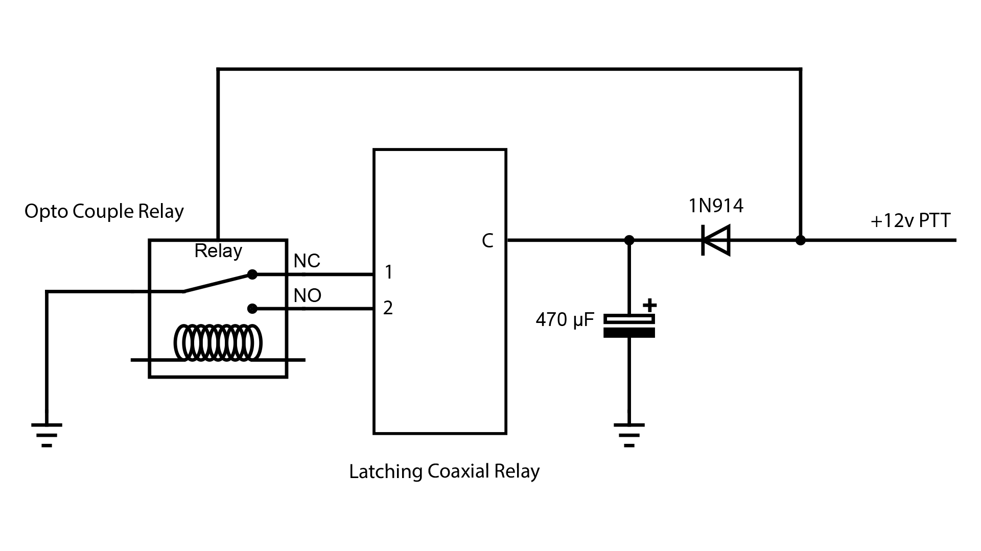
The circuit above is for a common positive relay.
Latching coaxial relays are common. They often have a common +, and grounding input 1 or 2 causes the relay to switch and latch in the opposite direction. Leaving the coil energised is not ideal. It will consume anywhere between 100 to 250mA, generate heat, and shorten the life of the coil, so it’s best to turn it off when in receive. In this circuit, the relay is left energised when transmitting and de-energised to receive.
When the PTT is pressed, +12v flows through the small signal diode and charges the 470uF electrolytic. It also powers the latching relay through the common connector. 12v is also fed to an optocoupled relay causing that relay to energise. This switches the coaxial relay into the TX position. It’s this optocoupler relay that will switch the coaxial relay to the RX position.
When the PTT is released, +12v is removed from the Optocoupled relay causing it to ground the other pin or the RX pin on the latched coaxial relay. The 470uF capacitor discharges through the coaxial relay staying charged long enough to latch the relay into its RX position. This capacitor is not critical and can be as low as 100uF, but I found 470uF was best for my coaxial relay.
Parts list
1 x 470uF electrolytic capacitor – Jaycar
1 x 1N914 small signal diode – Jaycar
a 12v Optocoupled Relay. Careful as many are 5v for Arduinos.
(You could always use a 5.1v Zenner diode to drop the voltage)
I have these 12v Optocoupled relays in the shack shop.
The crux of this latching coaxial relay circuit was built by Neil VK3BCU and Rob VK3KRD. Both had finessed the circuit having built many transverters over time. I needed this circuit as I had run out of failsafe relays for my latest project. It’s on my site so it doesn’t get lost and so others may use this clever circuit on their next microwave project.
The Minikites EME166 sequencer offers a reliable +12v source to switch a coaxial relay. It has 1 RX and 3 TX outputs. Ideal for adding PAs and preamps to transverters.
Pulse circuit – 12v common negative latching coaxial relay

Some latching relays don’t like constant voltage applied to them. This Ducommun coax relay will draw 220 mA continuously which converts to heat. In the case of this relay, the heat is substantial. Turning the volts off after you’ve switched to TX or RX will prolong the life of the relay.
This circuit is for a common negative latching relay. It provides a brief pulse to latch the relay. When the 12v is removed, the electrolytic is discharged via the 560 ohm resistor and LED. The LED colour can be indicative of the circuit’s function. Green for RX and red for TX etc.

Intefacing a latching relay with a Kuhne transverter

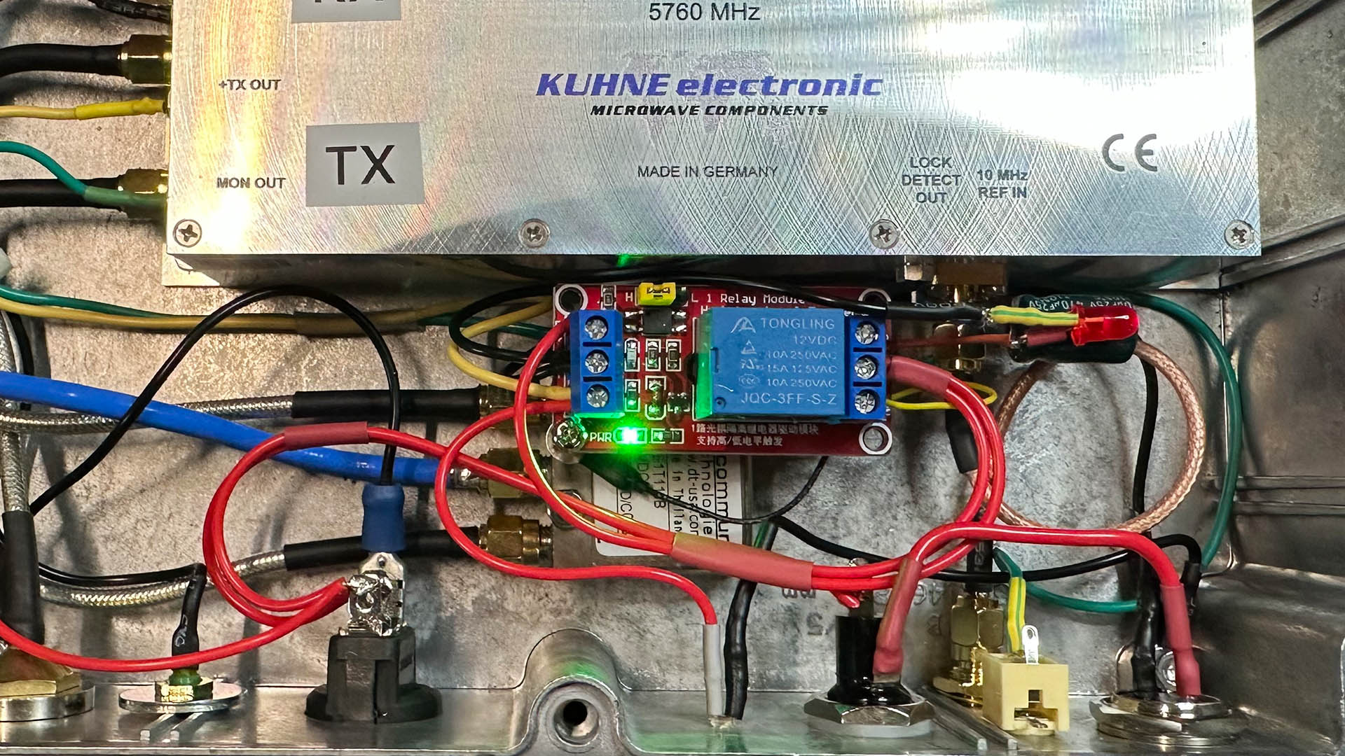
A recent transverter build required a little bit of creative thinking to switch the TX/RX relay without a sequencer. The Kuhne transverter has a TX 12v out so the circuit uses this 400mA maximum output to switch a 12v opto relay.
The TX side of the optical relay applies a constant 12v to the coaxial relay. The coaxial relay draws 220mA on if 12v is left on regardless of TX or RX. When in RX, the pulse circuit kicks in and applies a momentary 12v on the RX pole and causing the coax relay to switch into receive. After the pulse, there is no residual current flowing through the coax relay eliminating needless current draw and reducing the life of the relay. It’s also better for batteries when operating portable.


