
18 Nov Latching coaxial relay switching
Last Updated on August 6, 2024
Pulse switching of latching coaxial relays for microwave
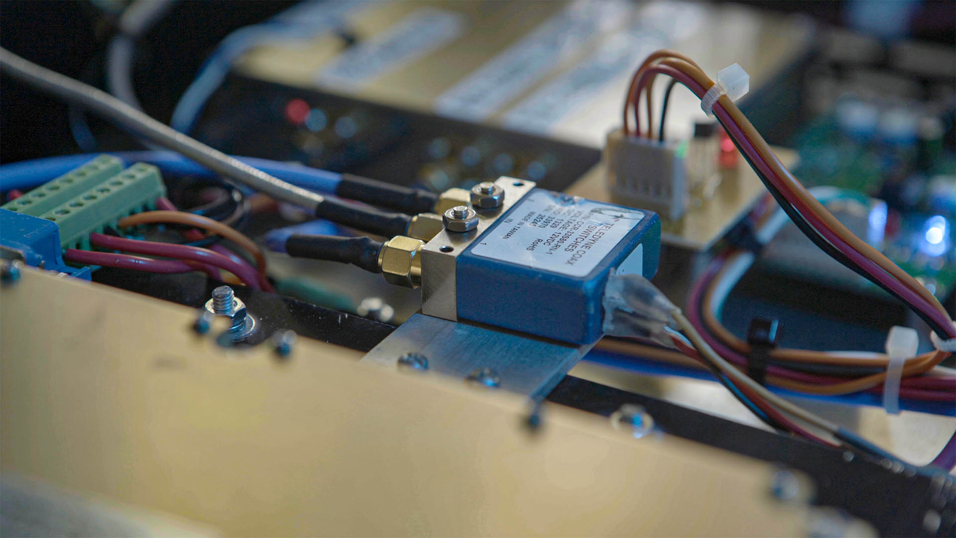
A latching coaxial relay is a type of relay that is specifically designed for use in RF (radio frequency) and microwave applications. A relay is an electrical switch that is operated by an electromagnet, and it is used to control the flow of electric current in a circuit. In the case of a coaxial relay, it is designed to handle radio frequency signals and is often used in applications such as RF switching.
The term “latching” refers to the relay’s ability to maintain its state (either open or closed) without the continuous application of power. Latching relays have two stable states and remain in one of those states until a specific pulse or signal is applied to switch to the other state. This is in contrast to non-latching relays, which require a constant application of power to maintain a particular state. There is no normally open (NO) or normally closed (NC) state with latching relays.
A latching coaxial relay works by using a latching mechanism to maintain its state (either open or closed) without the continuous application of power.
Latching Mechanism: The relay has a latching mechanism that allows it to stay in one of two stable states without the need for a continuous power supply. This is often achieved through the use of mechanical or magnetic means. Once the relay is set to a particular state, it will stay in that state until a specific pulse or signal is applied to switch it to the other state.

In summary, a latching coaxial relay uses a latching mechanism to maintain its state, and it can be switched between two stable states by applying a control signal. This design is advantageous in applications where power consumption needs to be minimized, and the relay needs to maintain its state without a continuous power source.
The Circuit
The circuit below is for 12 volt common negative relays only!
The Latching coaxial relay switching circuit is quite straightforward.
The left side of the circuit provides a pulse to switch the coax relay transmit, and the right provides a pulse to switch back to receive. Sequencers, such as the Minikits EME166, provide a +12v output when in receive, and three +12v outputs when in transmit. +12v TX is applied to pin 1 of external connector U3 while +12v RX is applied to pin 2.
The two electrolytic capacitors are charged from the respective +12v from the sequencer and then quickly discharge through the coaxial relay in the form of a pulse to change the relay from one side to the other. In effect switching the latching coaxial relay.
The two LEDs in the circuit act solely as a visual indicator showing which side is energised. The two 1N4001 diodes are flyback diodes across the relay to stop any back EMF should it be generated and that’s as complicated as it gets. The R1 and C1 values (which are the same as the R4 and C2 values) were chosen to suit the Ducommun 2SE1T11JB 12v coaxial relays. The relay switches using voltages anywhere between 7v and 15v from a sequencer.

Parts List
Most, if not all of the parts required for this project you should have in the shack.

Completed Kit
Relay out (top centre) with TX / RX 12 volts from a sequencer (lower left) and a common negative (lower right).


This PCB can be easily mounted wherever it’s needed using four 3mm nuts and bolts.
Time to Experiment
If you’re not using 12v, or you have a different relay, then you may want to alter some of the component values. I’ve used a variety of 12v common negative relays over many projects all with the same circuit. In some instances, you may want to increase the capacitance of C1 and C3. Rob VK3KRD has found 1000uF capacitors work well for the type of relays he was using. Also, if you’re changing supply voltage, consider the resistor values in series with the LEDs.
Here’s a recent build of a 10 GHz transverter. Note the large capacitor and green LED in some heat shrink behind the sequencer. Click the picture to enlarge it. This is the no-circuit board way I used to build the relay switching electronics which worked but was not ideal. The coaxial relay is fixed under the sequencer.
There’s plenty of room in this box to install the switching PCB above the interlinking coax.
If you have a latching relay and only want to convert it to a failsafe-style relay, check out this post on converting a latching coaxial relay to failsafe behaviour. Keep in mind that these relays draw around 220 mA and will get hot if you leave volts on them for any lengthy period of time as well as potentially shortening the life of the relay, you’ll flatten your battery faster if you’re working portable.

Overall, the board draws 20 mA which is the current the LEDs draw on the board. You’re only really using it when you push or let go of the PTT. The relay has no volts applied either, except during changeover, which means no heat and minimal power usage.