
08 Dec Callsign beeper CW kit interface for microwave path lineups
Last Updated on June 13, 2024
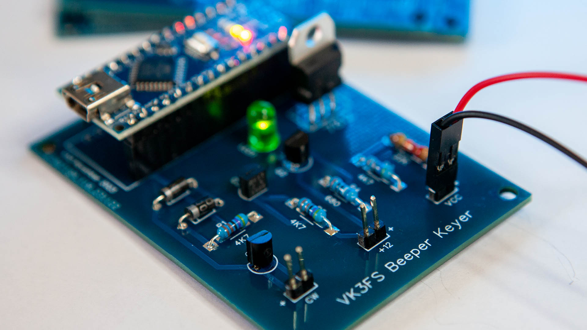
Callsign beeper CW kit interface
This is an Arduino-based callsign keyer or beeper that connects directly to the CW jack of your radio. Use it for microwave path lineups. It also has a +12v output which can be used as a driver stage for a GALI84 or similar, or just a visual indicator on the side of an enclosure.
This callsign beeper CW kit consists of a programmed Arduino with your callsign and a PCB only which will take you a few minutes to assemble from parts you’ll most likely have in your shack or a trip to Jaycar or Altronics. The beeper generates a string of ‘T’s at 25wpm (50 or 60 or so) followed by your callsign then keys on for 5 seconds before repeating. The sketch is available for download if you wish to make changes.
The circuit consists of an Arduino Nano which I’ve used pins only on one side of the device as well as a 7812 to provide a constant 12v to the Arduino, This saves on header pins, but that’s just me. You can always use header pins on both sides. The rest of the electronics converts the 5v output on pin 16 to switched VCC at no more than 100mA on the collector of the 2N3905. If you want more current, you could swap out the 2N3905 for a 2N4402 for VCC at 500mA.
The 2N2222 acts as a switch to ground to complete the CW circuit in your radio.


This Callsign beeper CW circuit utilises the Arduino Nano. If you’re familiar with these. or even just keen to experiment, they’re a great way to automate any project in the shack. This PCB will take just moments to populate. When complete, it can be built into your transverter, or a small box, ready to plug into the CW jack on your radio any time you need a beeper. The parts for this project are readily available from the shack cupboard of local electronics retailer. It woks well in many older radios such as the Icom IC-275/475 series or even the IC-705.
From breadboard to PCB

If building uWave gear has taught me anything, it’s that spares are important. Whether it’s components or fully built-up spare boards, chances are something will fail down the track for no obvious reason. This happened to me on a hill recently when 3 FETs in a sequencer decided to self-destruct for a reason not immediately apparent. Swapping out the board with a pre-built spare took minutes leaving the faulty board to be repaired and readied as the next spare.
With that in mind, I decided to make some PCBs of the project for easy swapping out if required. Also, having the Arduino Nano in a header socket enables it to be swapped out easily if it needs to be reprogrammed for whatever reason. These boards will also come in handy for future projects as well. If you’re in Australia, you can buy the PCB and programmed Arduino if you like.
Parts List
1 x Arduino Nano
1 x 7812 12v regulator
3 x 4K7 1/4W resistors
1 x 22K 1/4W resistor
1 x 680R 1/4W resistor
1 x 3mm LED
2 x 1N4148 small signal diodes
1 x 2N2222
1 x 2N3904
1 x 2N3905
2 x 15-pin headers (Nano)
3 x 2-pin headers (IO)

This Arduino Callsign beeper beacon controller uses a 2N3905 to switch VCC to the output. It can deliver 100mA. If you need more, you could swap it out for a 2N4402 which can handle up to 500mA. This device is designed for use as a general-purpose amplifier and switches requiring collector currents to 500 mA if you’re using the 2N4402 or 100 mA if you’re using the 2N3905 via U2. The CW output,U3, is designed to connect to the CW jack on your radio. It works just fine on ground-switched keys such as the IC-475 and IC-275 radios.
Finished beeper mounted on the side of the IC-475
I decided to mount the Arduino Callsign beeper beacon into a zippy box from Jaycar (HB6013) and utilise the mounting bracket screw holes on the side of the IC-475 as a sturdy mount for the box.
Two M5 screws 10mm apart did the trick. If you go down a similar path make sure the screws you use aren’t too long and damage any of the electronics inside the radio. And in good news, the accessories jack on this series of radios has 13.8v DC available on pin 7 which means the whole installation can be self-contained.
Data Sheets and Arduino Sketch
Fairchild transistor datasheets for the 2N3904, 2N3905 and 2N4402 general purpose transistors are also provided for download.
The download below contains the Arduino sketch for the beeper. Modify it to fit your needs. The file is commented with where to change the parameters for your station. You can also change the CW speed and mark space ratio if you like.
A shoutout and thanks to Mark VandeWettering K6HX whos code is the base of this sketch.